Pneumatic Comparator – Parts, Working, Types, How to Select, Advantages ,Disadvantages, And Pneumatic Vs Mechanical Comparator
A comparator is an instrument that is used to measure the precision of a given component by comparing the dimensions of a given component with the actual working standard.
Pneumatic means air, and in pneumatic comparators, the air is used for magnification of the measured reading.
A pneumatic comparator works on the principle that if an air jet is in close proximity to a surface, then the flow of air out of that jet is restricted, which changes the air pressure in the system supplying the jet.

Parts of Pneumatic Comparator:-
1 Compressor:-
The compressor is the heart of a pneumatic comparator. A compressor is used to compress the air, and compressed air is present inside the compressor.
Filter:-
After the compressor, the filter is present. In this filter, all the dust particles present in the air are separated from the air, and clean air passes through this filter.
Tank:-
After the air passes through the filter, the air pipe divides into two paths. Some air goes into the tank, and some air goes to the orifice.
Orifice:-
This orifice leads to the second chamber.
Manometer:-
The second chamber has an outlet to a glass manometer tube.
Gauging Head:-
The second chamber is also connected by a flexible tube to the gauging head. This gauging head has two restricting jets that are used to check unevenness or irregularities in the workpiece.
Working of Pneumatic Comparator:-
- In this comparator, compressed air is used as an operating medium. At first, the air is compressed in the air compressor,
- Then the compressed air from the compressor passes through the air filter.
- All the dust particles present in the air are separated from the air in the air filter, and only pure air passes through the filter.
- After passing through the filter, the air pipe is divided into two ways and some air goes to the tank, and some air goes to the restricted jet or orifice.
- As air enters the water tank, bubbles will be created in the tank, and the rest of the air that passes through the orifice reaches the gauging head through a flexible tube.
- A controlled amount of air passes through the orifice with the required pressure in it.
- At this time, the manometer shows the initial pressure by which the air passes to the gauging head.
- The workpiece or the job is reciprocated along the gauging head.
- This gauge head is generally used to examine the internal diameter of a cylinder, whether it has irregularities or not in its internal diameter.
- This gauge head is inserted into the cylinder, and both jets in the gauge head face towards the internal wall of the cylinder.
- The internal wall of the cylinder restricts the air coming out of the jet of the gauging head.
- Based on the gap between the jet and the internal wall of the cylinder, back pressure will be created as the internal wall restricts the air coming from the jet.
- When the backpressure is created, the air that is passing through the gauging head will return back and it will go inside the manometer tube and this backflow of air will push down the water inside the manometer.
- At first, a standard workpiece is taken in which the internal wall is perfectly flat. This standard workpiece is used to calibrate the pneumatic comparator. Using this standard workpiece, the water height in the manometer is adjusted so that it is equal to the height of water in the tank. This standard workpiece is known as a reference workpiece because it is used to get the reference pressure in the manometer.
- When the gauge head of the pneumatic comparator is placed inside a cylinder that is to be examined. The air hits the internal wall of the cylinder, and if there are any irregularities in the internal wall, the backpressure in the comparator is created, and the water inside the manometer is pushed down. Hence, the water level inside the manometer falls, and we get a height difference between the water level of the tank and the water level of the manometer. This height difference is denoted by ΔH.
- So if the ΔH value is high, then we can say that a greater amount of roughness is present at the position of the cylinder where the gauge head is placed.
- After that, the gauge head is placed in different positions inside the cylinder, and ΔH is noted for different points so that roughness throughout the cylinder can be measured.
- If ΔH is high for different points inside the workpiece, then this workpiece needs to be rejected.
- A pneumatic comparator is used when a large number of cylinders or workpieces need to be tested, i.e., when there is mass production of the workpiece and quality inspection needs to be done.
Types Of Pneumatic Comparator:-
There are mainly three types of Pneumatic Comparator:-
1) Flow or Velocity Type Pneumatic Comparator
2) Back-pressure type Pneumatic Comparator
3) Differential type Pneumatic Comparator
1) Flow or Velocity Type Pneumatic Comparator or force flow gauges:-
This type of pneumatic comparator works by sensing and indicating the momentary rate of airflow.
The flow is sensed using a glass tube with a tapered bore inside it. The glass tube is mounted over a graduated scale.
Inside the bore, a float is lifted by the airflow. The compressed air after filtering and pressure regulating unit flows through a glass tube which contains a small metal float.

After that, the compressed air flows through a plastic tube, which is located in the opposite direction with two identical holes to allow the air to escape.
The position of the float depends upon the amount of air flowing through the gauge head, and the air flowing through the gauge head depends upon the clearance between the bore to be measured and the gauging head.
2) Back pressure Type Pneumatic Comparator:-
In this type of pneumatic comparator, a jet orifice is placed very close to the workpiece, but the jet orifice does not touch the surface of the workpiece.
Compressed air is passed through the jet orifice to the workpiece to check the dimensions of the workpiece.

Main components of back-pressure pneumatic comparator:-
* Compressor
* Air filter
* Valve
* Water tank
* Manometer
* Flexible tube
* Workpiece
In this pneumatic compressor, the compressed air is passed through the air filter, and the dust particles and moisture are removed from the compressed air by the air filter.
This filtered air is sent to the valve, and after passing through the valve, the compressed air is passed over the water tank, and some part of the compressed air enters the water, and some part moves forward.
The air pressure over the water tank is denoted by P1, and this is called the main pressure.
After that, the compressed air is passed through the orifice A, and the pressure of air changes from P1 to P2 after passing through the orifice A. P2 is called the intermediate pressure.
The air is flown towards the workpiece with pressure P2 i.e the intermediate pressure.
Before reaching the workpiece, the compressed air passes through another orifice named orifice B.The pressure difference between P1 and P2 depends on orifice A and orifice B.
If a double orifice is used, then the formula below is used:-
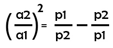
Here,
a1 and a2 are the areas of orifice1 and orifice 2.
And p1 and p2 are the main pressure and intermediate pressure.
The compressed air then reaches the workpiece, and if there is any defect or error in the workpiece dimension, a back pressure will be created and will flow upward through the flexible tube. Due to the back pressure, the liquid level in the manometer goes down, and this back pressure is measured using a scale that is calibrated on the manometer.
The level of error is proportional to the change in the liquid level of the manometer.
3) Differential Type Pneumatic Comparator:-
A differential-type pneumatic comparator is used to determine dimensional variations by measuring differences in back pressure, created by two air jets: one for a reference standard and one for the workpiece.
The components present in a differential type pneumatic comparator include a pressure regulator, compressor, air filter, control orifice, zero setting valve, pressure indicating device and measuring head.

At first, the air is compressed and then allowed to pass through the air filter and pressure regulator. After that, the air pressure is created and stabilised.
The air in the split channel flows at a constant pressure. Air flows through orifice 1 and reaches the measuring head through the channel ‘P’ at one end.
The air supplies also travel through the control orifice 2 to a zero adjusting valve via the channel.
The pressure indicating valve is present inside the airline. Here, the airline links the channels P and Q together.
First, it is adjusted using a workpiece. When the measuring head travels towards the workpiece, the measuring device pointer begins to turn away.
A decrease in the permission or constraint between the workpiece and measuring head will increase the pressure within the system, which leads to deflection.
How to select pneumatic comparator:-
1) It can be handled easily.
2) It should respond very quickly.
3) It should be compact.
4) It should give results quickly.
5) It must be of low cost
6) The weight of the comparator should be low.
7) Its maintenance should be low.
8) There should be no effect from the surroundings.
9) Its design should be strong and durable.
10) The comparator must have a linear scale so that it can be read easily and obtain a uniform response.
Advantages of Pneumatic Comparator:-
1) In the Pneumatic Comparator, high magnification can be achieved.
2) The gauging member does not come into direct contact with the part to be measured, and hence no wear and tear takes place on the gauging member or the workpiece.
3) The measuring is very small and does not cause any harm to the workpiece. Instead, it helps to clean dust, if present, from the part measured by the jet of air.
4) Due to a very small number of moving parts, the accuracy is high as there is very little friction and less inertia.
5) A pneumatic comparator is best for determining the ovalness and taper of the circular bores.
Disadvantages of Pneumatic Comparators:-
1) Different gauging heads are required for different dimensions.
2) The pneumatic comparator can require elaborate auxiliary equipment such as an accurate pressure regulator.
3) The scale is generally not uniform.
4) They are very sensitive to temperature and humidity changes.
5) This device is not easily portable and is rather involved in many industrial applications.
Difference between mechanical and pneumatic comparator:-
| S.No | Mechanical Comparator | Pneumatic Comparator |
| 1 | A mechanical comparator is a high-precision inspection instrument used in manufacturing to determine dimensional deviations of a workpiece by comparing it against a master standard. | It is also known as a microcator. |
| 2 | It is also known as the solex air gauge or solex pneumatic comparator. | It is faster than a mechanical comparator. |
| 3 | It works on high-pressure air, back pressure, valves, orifice, etc. | It is slower than a pneumatic comparator. |
| 4 | It is less precise. | It is more precise. |
| 5 | It is less expensive | It is more expensive. |
| 6 | A pneumatic comparator is a device that is used to measure the dimensions of the workpiece by comparing the dimensions of workpiece with the reference dimensions using air pressure. | It works on pinions, gears, linkages, springs, levers, etc |
| 7 | It needs more maintenance. | A pneumatic comparator is a device that is used to measure the dimensions of the workpiece by comparing the dimensions of the workpiece with the reference dimensions using air pressure. |